adding face tracking to my pico 4
and how i accidentally got into hardware development
After years of deliberation, I recently pulled the trigger and got myself a second-hand VR headset. Initially, I got a Quest 2, and after hopping on VRChat for a few moments, I immediately fell in love. There's something charming about the experience in VR that playing it on desktop mode just doesn't have.
Within the past year, I've accumulated hundreds of hours in game, took nearly 3,000 photos, and made lots of new friends. Being able to sit next to people and talk to them directly just feels different, in a good way. I get to use my body language to express more than words can.
And I love being able to do that so much to the point that I've spent thousands on full-body tracking equipment. Just so I can swing my legs in VR.
Cute, right? Of course! I love it so much. And if you're still reading this I know you do too. But there's one thing that bothers me about the experience. My avatar has such a cute face, but it's stuck in a perpetual state of expressionless stare. And I know I can change it, but there's only so much winking and blinking I can do with my controllers while I'm trying to have a conversation with someone.
So I looked into face tracking. And my wallet trembled in fear.
the state of face tracking hardware
There's something I forgot to tell you. I actually broke my Quest 2 a few months in, and the local repair shops took 2 weeks just to tell me they couldn't repair my headset. All the while I was itching to get back to getting headpats in VR. So I bought a Pico 4 as a replacement.
For $250 SGD second hand, it's a very solid piece of equipment, with pancake lenses, a balanced center of gravity. But it doesn't have eye tracking.
And the cheapest one that does? Probably a second hand Quest Pro that goes for $800, or a Vive Pro Eye which doesn't go around much here in Singapore. But with the VPE, the headset only has eye tracking, so you still need to look for the discontinued face tracker from the second hand market.
The choices are limited and there's not a lot of good options.
open source to the rescue?
So as it turns out there are two projects aiming to provide eye and face tracking, EyeTrackVR and Project Babble. Essentially, they provide the software including pre-trained models that will take in a video feed of your eyes and mouth, and output messages through OSC which will be recognized by VRChat as facial expressions.
Both projects also give out instructions on how to build the hardware that will attach to your VR headset. And so I got all the parts and built one myself.
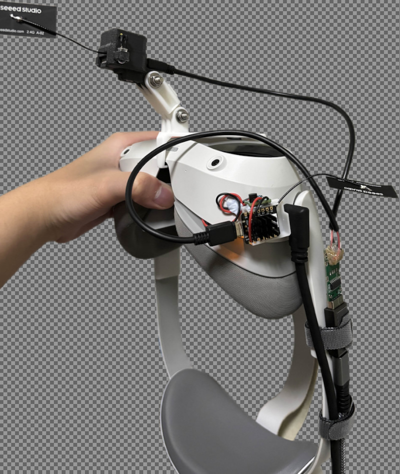
Yeah, it's not exactly the prettiest. There's wires all over the place, exposed components, multiple cables going towards the headset. It's not something I want to use every day.
However, as messy as this setup is, the tracking results are pretty good.
I was able to blink, move my eyes, control my ears with my frowning, stick out my tongue, and many more. I was quite pleased with the results, but there were a few issues with this mishmashed prototype build that I want to fix.
the issues
The contraption pictured above was a prototype build, and it had a couple of issues.
- There were cables everywhere, and things were stuck on with Blu-Tack, which makes handling the headset difficult
- The 3D printed plastic mounts were not fitted correctly and the boards would slide around and disconnect mid-session
- I'm running two cables to my headset; one for the wired PCVR stream and the other for the eye and face tracking stuffs
- I've only added tracking to one eye, which means I can't wink, only blink
I could go on, but those are the big issues preventing me from keeping this setup for longer than was necessary to record some demo videos.
So as a curious fox, I set out to build the perfect solution that will solve all of my problems.
enter: usb hub
One thing I wanted to have is a USB hub attached to my headset, with a looong cable towards my PC. But all of the USB hubs I found on AliExpress are either very dodgy with a short "dongle" USB cable, or heavy duty ones that's too overkill for my use case.
I just wanted a cheap USB hub with a Type-C port to connect to my PC. And nobody's making those that are also cheap.
So I made my own.
With zero experience, I opened KiCad and started designing something resembling a USB hub, with pads for the ESP32 to mount onto. I sent it out to JLCPCB, and a week later, I got my board delivered.
Of course, I plugged it in and... it didn't work! When I plugged it into
my PC, dmesg did show something but it kept disconnecting,
and it wasn't really working as a USB hub at all. Well, the power did go
through, but there's no data flowing.
As it turns out, you can't just draw traces from the USB ports to the hub chip and from the hub chip to the destinations. There are certain rules and constraints that I have to follow to maintain signal integrity. And as a software engineer, I've never had to deal with this before.
I can't just edit the code, compile it, and see what's wrong within a 30-second feedback loop. I only get to see the results of what I did after sending my board out for production and waiting a week for it to be built and shipped. Plus it costs me money every single time.
So I spent the next few weeks reading up on the USB 2.0 spec, watching Phil's Lab and Altium Academy videos on YouTube. I found out that there's this thing called 'characteristic impedance' and that for USB 2.0 data lines, it is specified to be 90Ω. I don't really understand the full technical details of how it works, but essentially, you want your traces to be next to each other, at a calculated width and spacing. And you want them to travel within and over a solid ground plane.
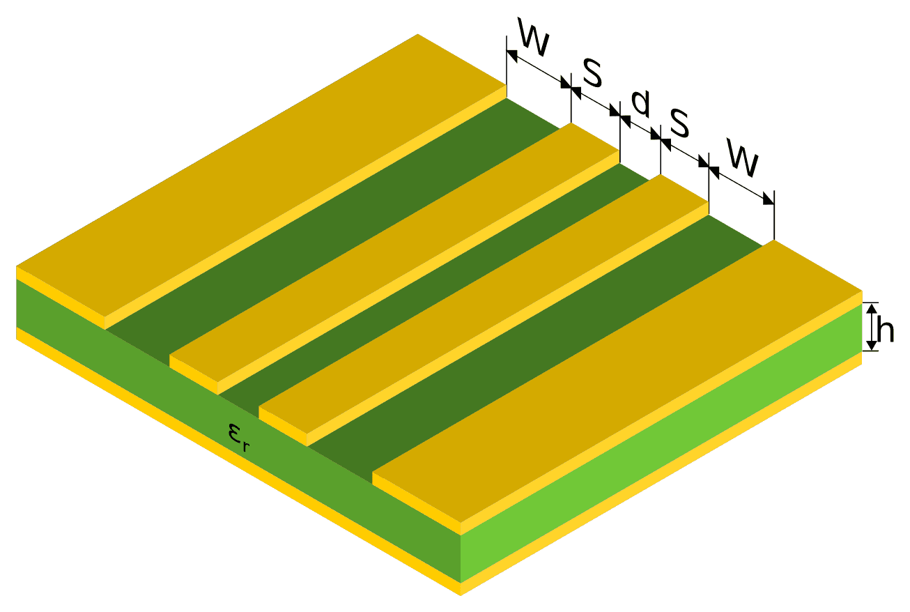
Image above taken from this StackOverflow question. If you imagine a cutout of a PCB, there's copper on the top and bottom layers, separated by the green stuff in between. The material, spacing, and thickness of the copper and insulator need to be taken into account when designing circuits.
Conveniently, JLCPCB has a calculator on their website which tells you how you should route your traces if you want to hit a specific impedance requirement.
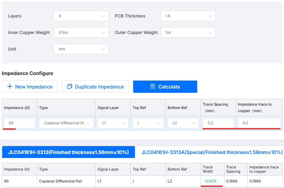
Using a 4-layer board and the specific board stackup that I'll be ordering from JLCPCB, and for a Coplanar Differential Pair with the specified target impedance and spacing, it tells me to make my traces 0.1435mm wide. So if you imagine the visualisation above,
d = 0.2mm
W = 0.2mm
S = 0.145mm
So I completely redesigned my board using the correct calculations, and used a different chip for the USB hub: the CH334F. It has fewer pins and is really simple to integrate, which makes it less likely for me to mess up my next prototype.
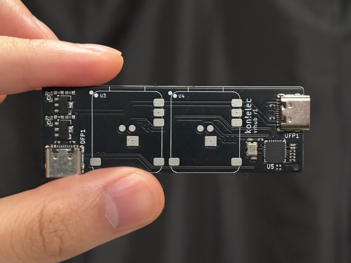
After double and triple checking my design, I pulled the trigger and sent the order out for production. One week later, I got my first working prototype!
After verifying that the USB hub worked, I soldered the 2x Xiao ESP32 S3 Sense boards on top, and just like magic, it worked too!
You might wonder why the first prototype was in the Sleek Black while my second prototype is in Circuit Board Green. Well, it's actually quite straightforward. The black one was Cool, but the green one is Cheap. And after my first mistake, I've learned to appreciate cheap more than cool.
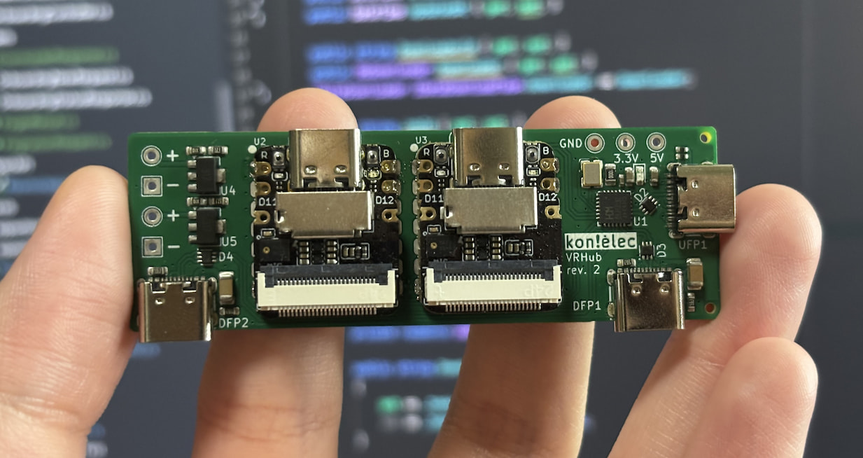
This board features a Type-C port on the right side to connect to my computer, and two Type-C ports below to connect to devices, such as the mouth tracker and the headset. The two ESP32s are soldered directly onto the board using a reflow method, connecting the power and data pins to the board pads.
This resulted in a setup that looks so much cleaner. Only a single wire needs to go from my PC to the headset, and everything else is centrally managed by the board.
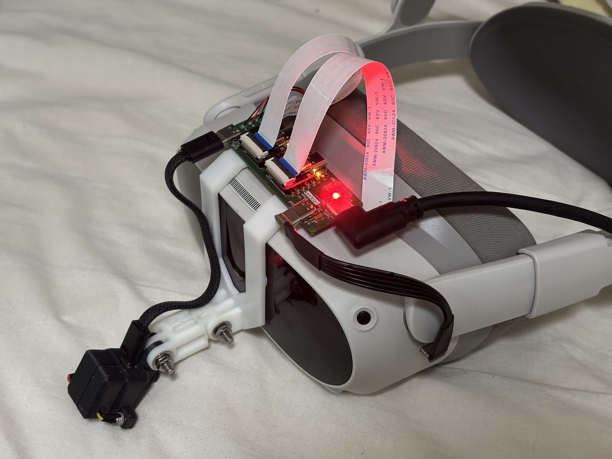
This design allowed me to have both eyes connected and tracking, which lets me do stuff link wink.

the end?
Now, that would be a pretty good point to end this post, with me having a nice and working prototype, which fulfills all of my needs, and is perfect in every way possible, and we all live happily ever after.
If only that's the case. Oh, no, we are just barely scratching the surface here.
The thing is, using this USB hub, my Pico 4 only draws at most 500mA of power, which is the standard for USB 2.0. Although the power supply upstream can push out more, the headset refuses to draw that power and would run out of battery as if it wasn't plugged in at all.
So now I'm stuck between a few options.
- Accept that my headset will be running on battery power
- Run a charging cable to my headset in addition to the USB cable to the eye and face tracking board
- Incorporate USB-C Power Delivery into my VRHub board
Of course, being the stubborn fox that I am, I decided to go on another adventure. But that's for another blog post. This one already took nearly a year to publish, so the next part will have to wait.